

How To Fill Hydraulic Lifters With Oil
How to bench bleed hydraulic valve lifters

A quick guide on removing air from hydraulic valve lifters (haemorrhage), such as those used on the fuel-injected VW Type ii bus.
Why do hydraulic lifters need bleeding?
The main goal is to ensure that before installation, hydraulic lifters are properly filled with oil and oil only. Past bleeding them, unwanted air is removed from the lifters.
The uncompressible oil content in their pressure sleeping accommodation is what makes them finer work as solid lifters during operation. If air (compressible gas) comes in, the mixture volition create a compressible cushion in the pressure sleeping accommodation. As a result, the lifters volition be springy and will no longer human activity equally solid ones. If the lifters are fully functional, they should somewhen refill/bleed while driving the bus automatically, merely information technology might take a while and they volition be noisier until then.
💡 You tin hands examination if some air (or actually just air) is nowadays in a hydraulic lifter. Simply push on the pushrod socket underneath the lock ring with your thumb. If y'all tin depress it, information technology needs bleeding out the air within. If you cannot depress it, and then the lifter is fine.
This is not an essential maintenance procedure, though. In fact, you tin can bleed the lifters on the vehicle. In that location are multiple sources with instructions on how to do it (that ratwell article is ane for instance), but it'south beyond the scope of this guide. Bench haemorrhage lifters volition assist y'all with setting their preload when adjusting the valves, as you will be able to better feel the point of solid contact with the pushrod. Empty or partially air-filled lifters will have a spongy contact signal, which more often than not requires more experience to find.
Likewise, it'southward never a bad idea to make clean them up subsequently 40 years of utilize.
How they're put together
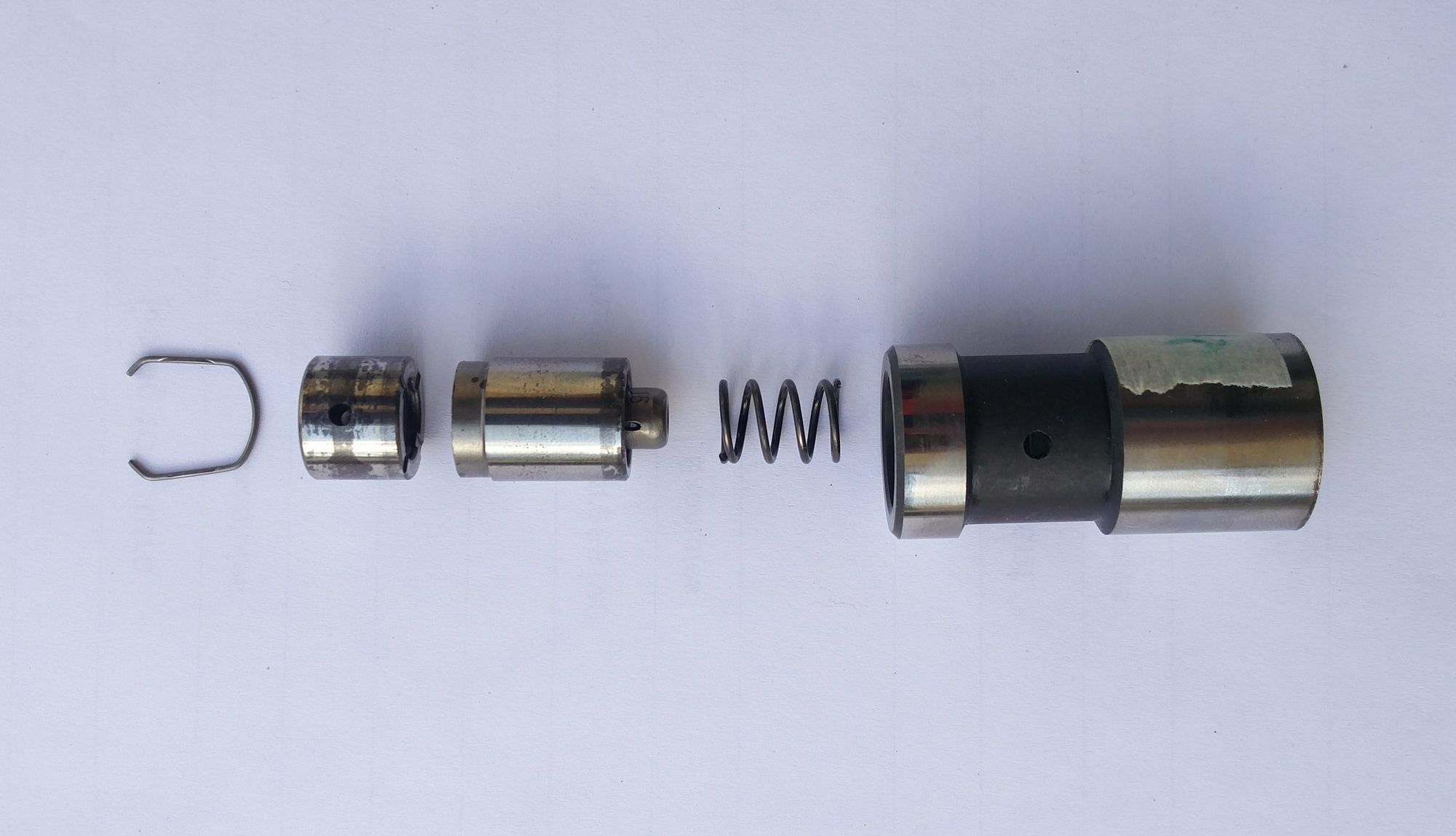
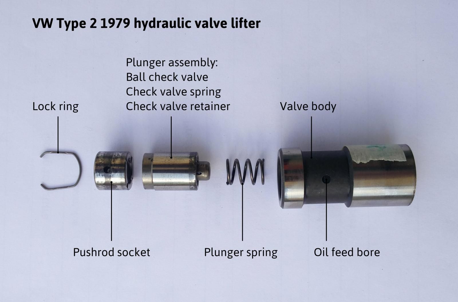
Here are some diagrams to sympathize the different parts of a lifter and how they are assembled:
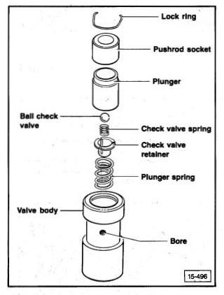
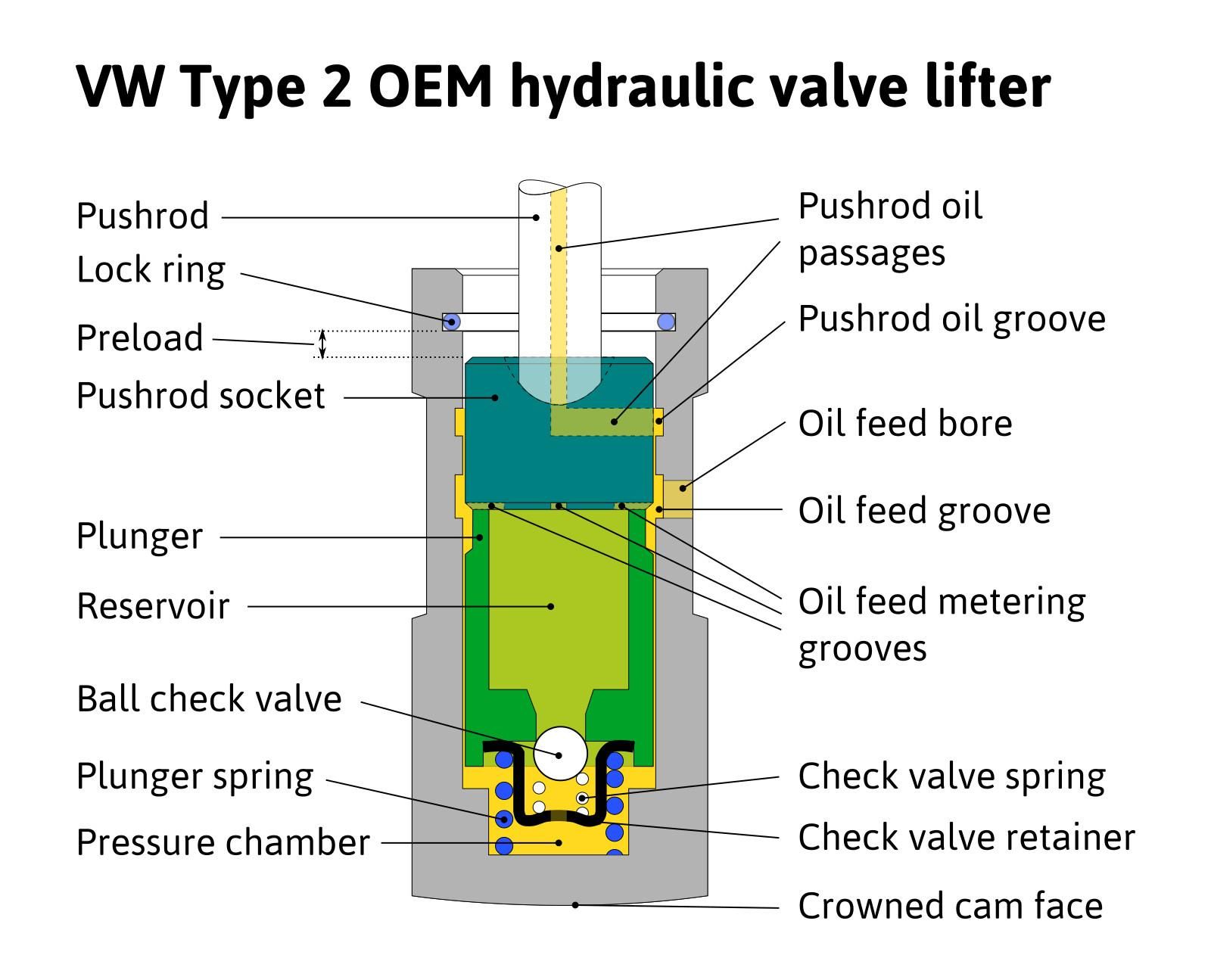
Notice that:
- the plunger and pushrod socket exercise not actually contact the lifter torso. Information technology's a precision fit that allows for controlled oil haemorrhage and enables the self-adjusting function of the lifter;
- the pushrod oil passage is exclusively fed past oil bleeding. That surprised me, as I thought a mechanism that allowed more oil catamenia would be needed. That's a topic for another thread though;
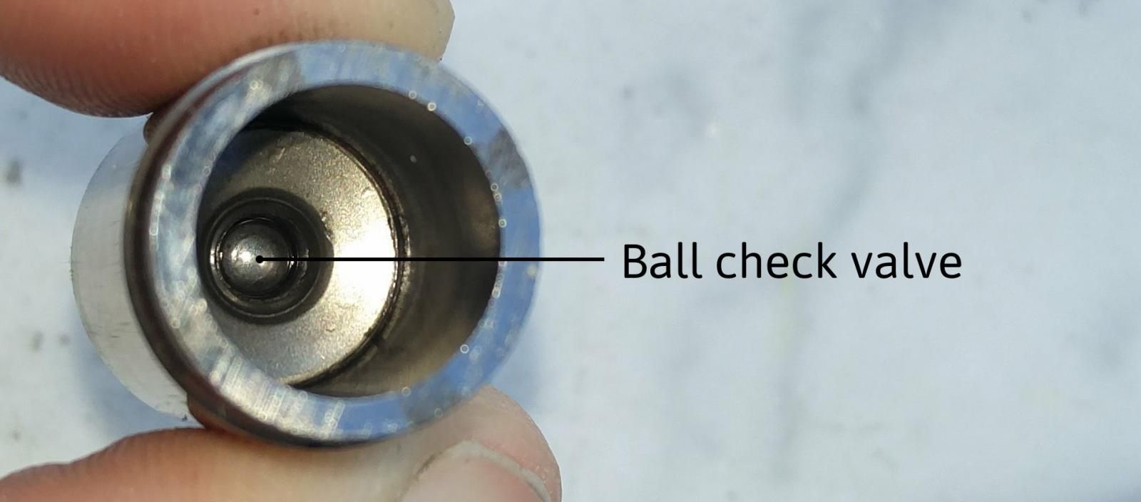
- the pressure bedroom is refilled via the 4 oil feed metering grooves on the pushrod socket, when the ball check valve is open.
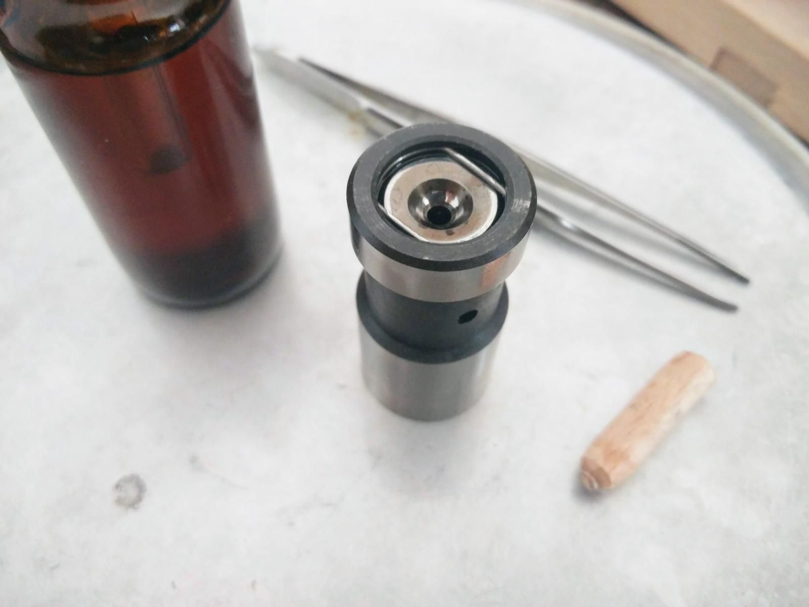
And my actual lifters, disassembled. Notice that the ball check valve is part of the plunger assembly. In that location is no need to take it apart. Also notice the oil metering grooves at the base of the pushrod socket.
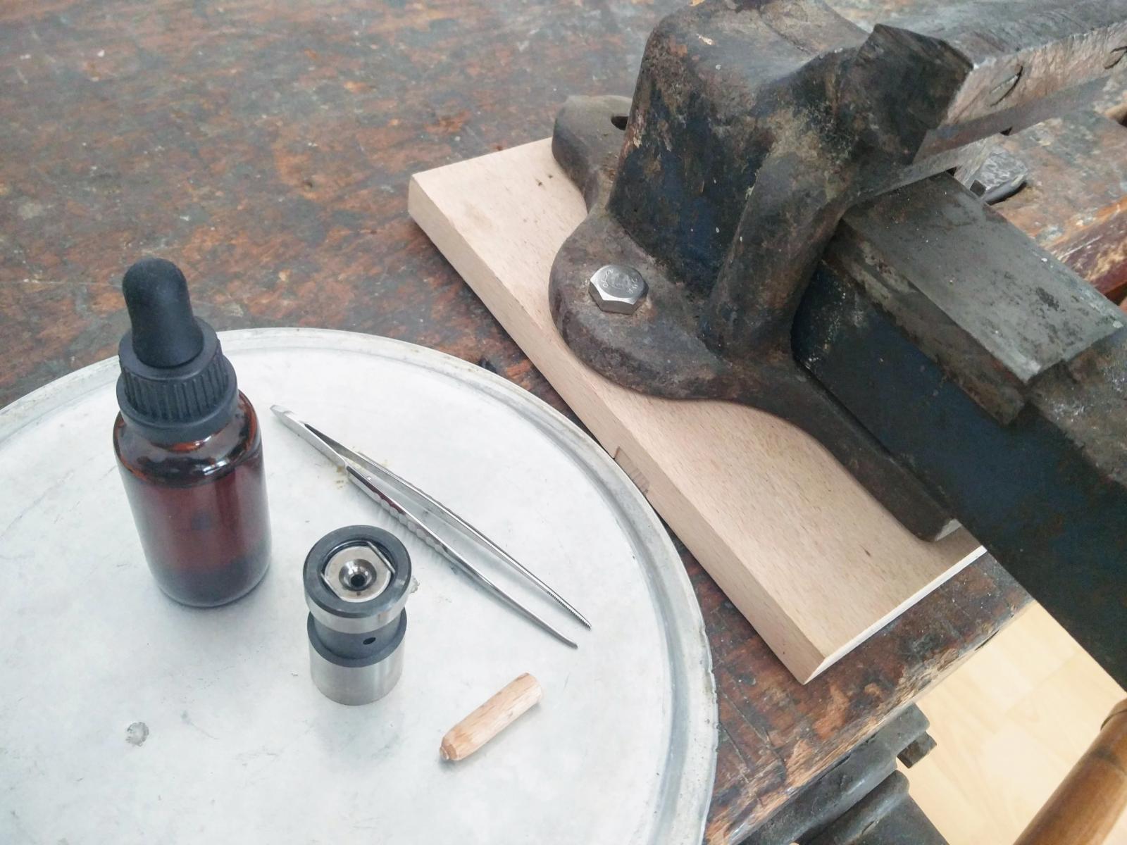
- Bench vise
- Tweezers
- Engine oil
- Hydraulic valve lifter to bleed
- Hardwood dowel
Tweezers – Utilize your option of tool instead of tweezers if you will. The reason I like them is that they let me remove the lock ring, extract the plunger and push the ball check valve when either removing or inserting the plunger. All in 1 tool.
Dowel – The Bentley manual recommends using an former valve guide or sawn-off pushrod to push the socket back in place to insert the lock ring while on the vise. I did not take an old pushrod laying around, and fifty-fifty and so, I doubt I would take sacrificed it unless information technology were bent. A hardwood dowel (e.1000. beech or oak) does the job just fine and it'southward easier to saw. Just make sure that it is long plenty to give you room to insert the lock ring while on the vise, simply brusk enough not to snap out of the vise. You lot can use a pencil sharpener to sparse and round the end that goes into the socket for a better fit. Also, if I were to do this ofttimes, I would probably fabricate a pocket-size base of operations for the dowel for information technology to be perpendicular and have better stability on the vise.
Engine oil – I used a small canteen with a pipette. Non strictly necessary. I used it more for the fact that there is less chance of oil spilling than with a large container. Nevertheless, the pipette proved quite useful for precisely filling up to the bleed pigsty.
The procedure
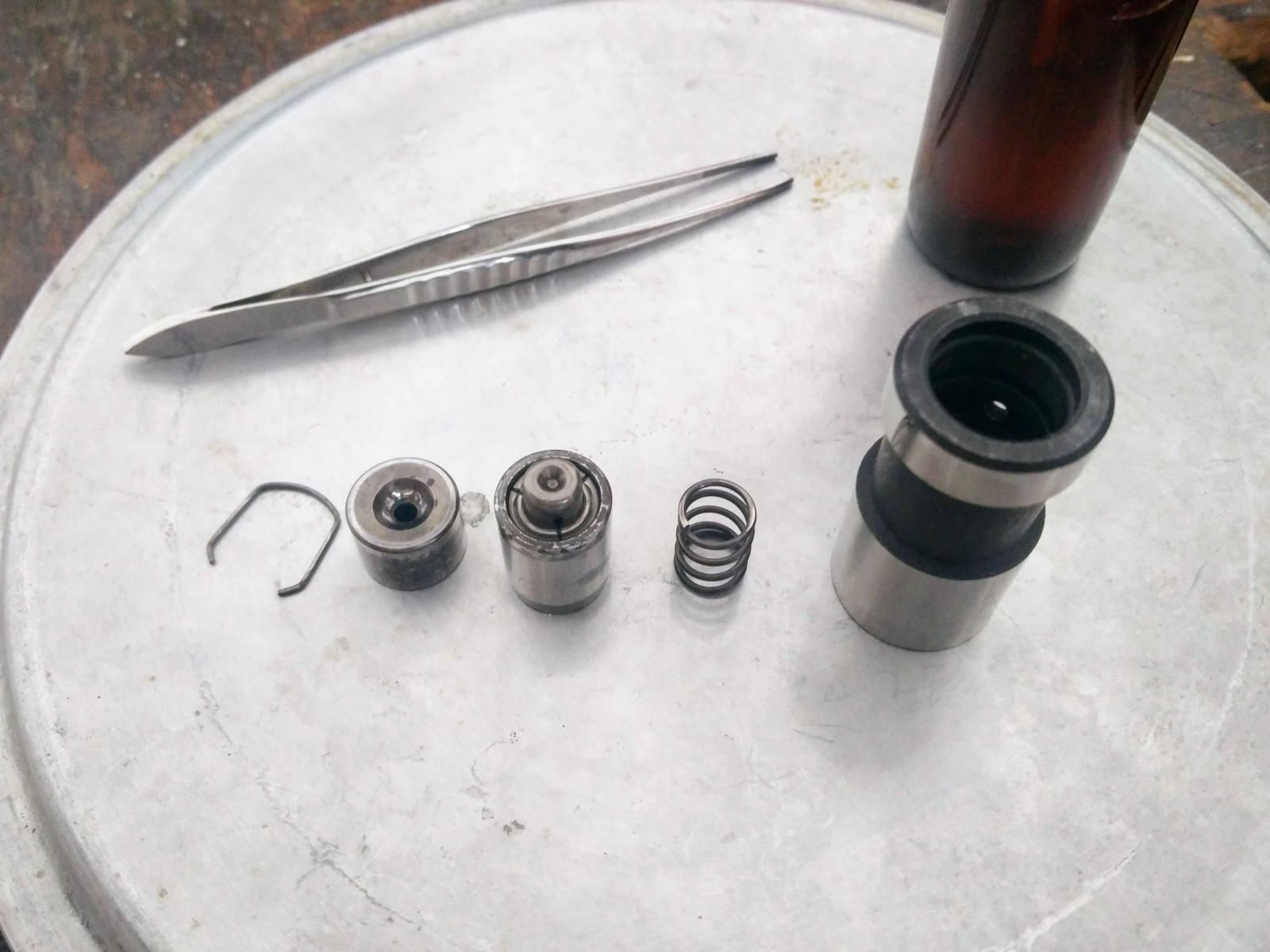
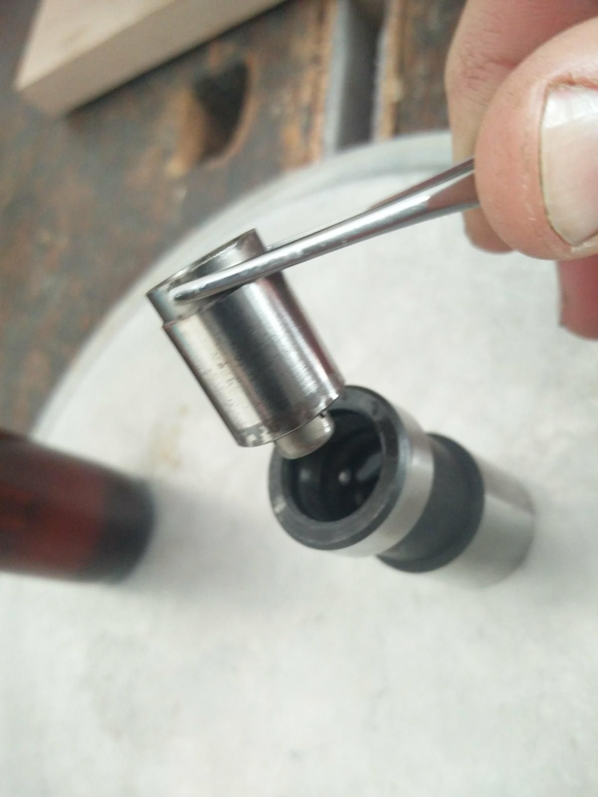
- Pry out the lock band
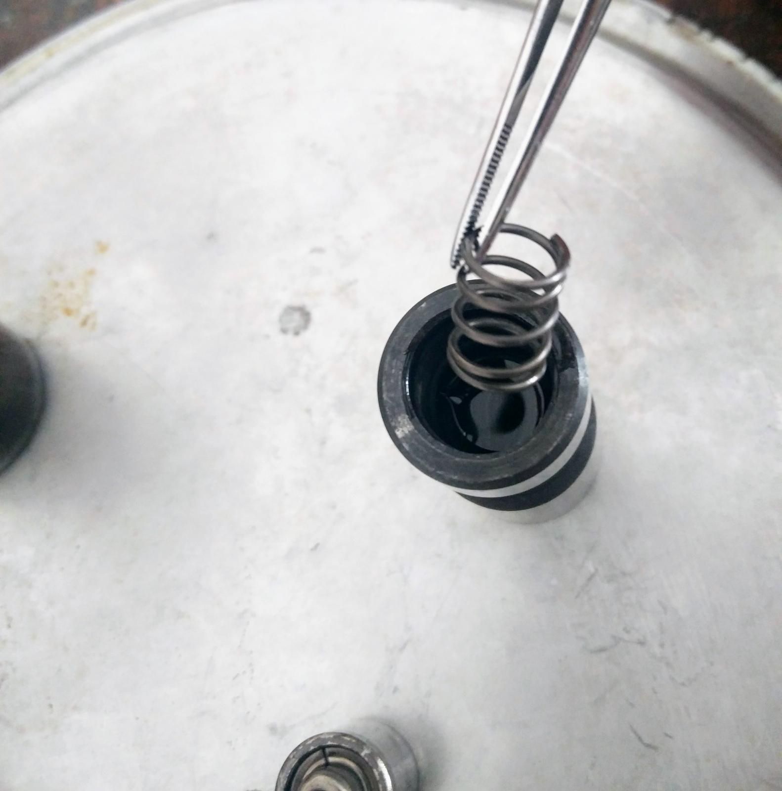
- Remove pushrod socket, plunger assembly and plunger spring
👉 While you are at it, exercise clean the lifter with your solvent of choice. Small particles of metallic like to collect at the bottom of the force per unit area bedchamber, the ball check valve tin can likewise stick with varnish.
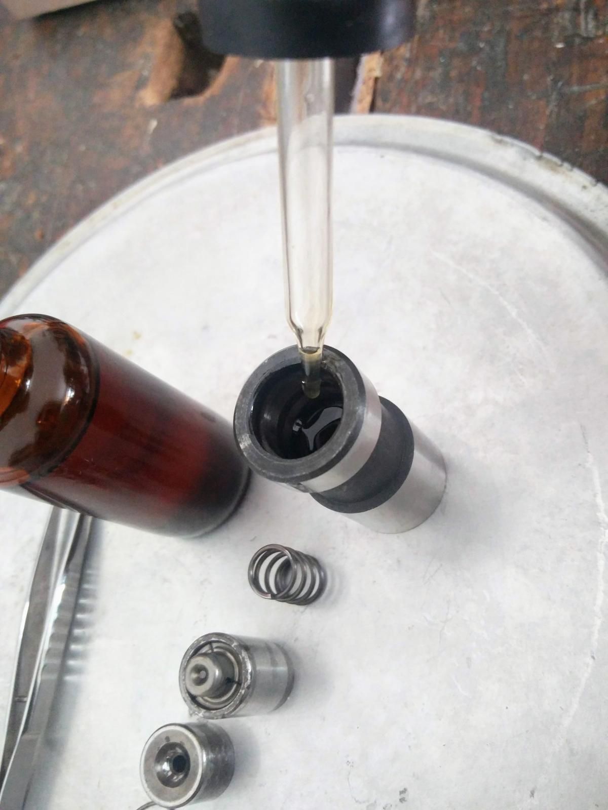
- Fill valve lifter torso with oil up to drain hole
- Insert plunger jump
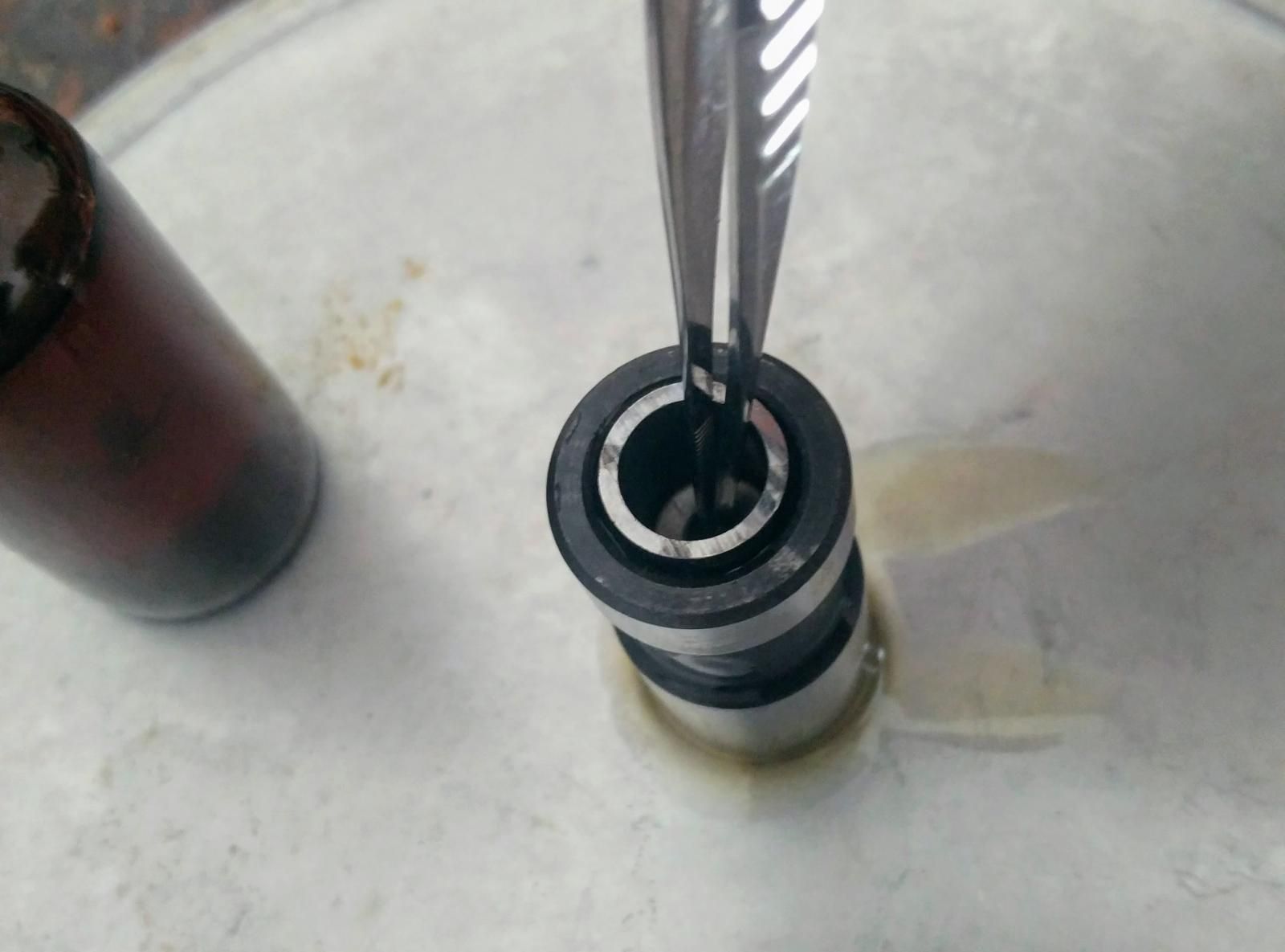
- Install plunger assembly and push downward; at the aforementioned time, open ball check valve with scribe
👉 Observe oil starting to bleed out of the hole in the lifter trunk. Proceed pushing downwardly until you come across some resistance. This volition mostly coincide with the plunger acme but starting to be submerged.
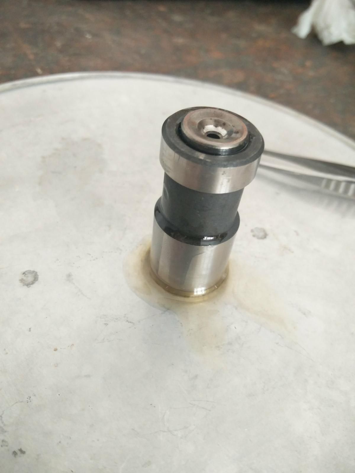
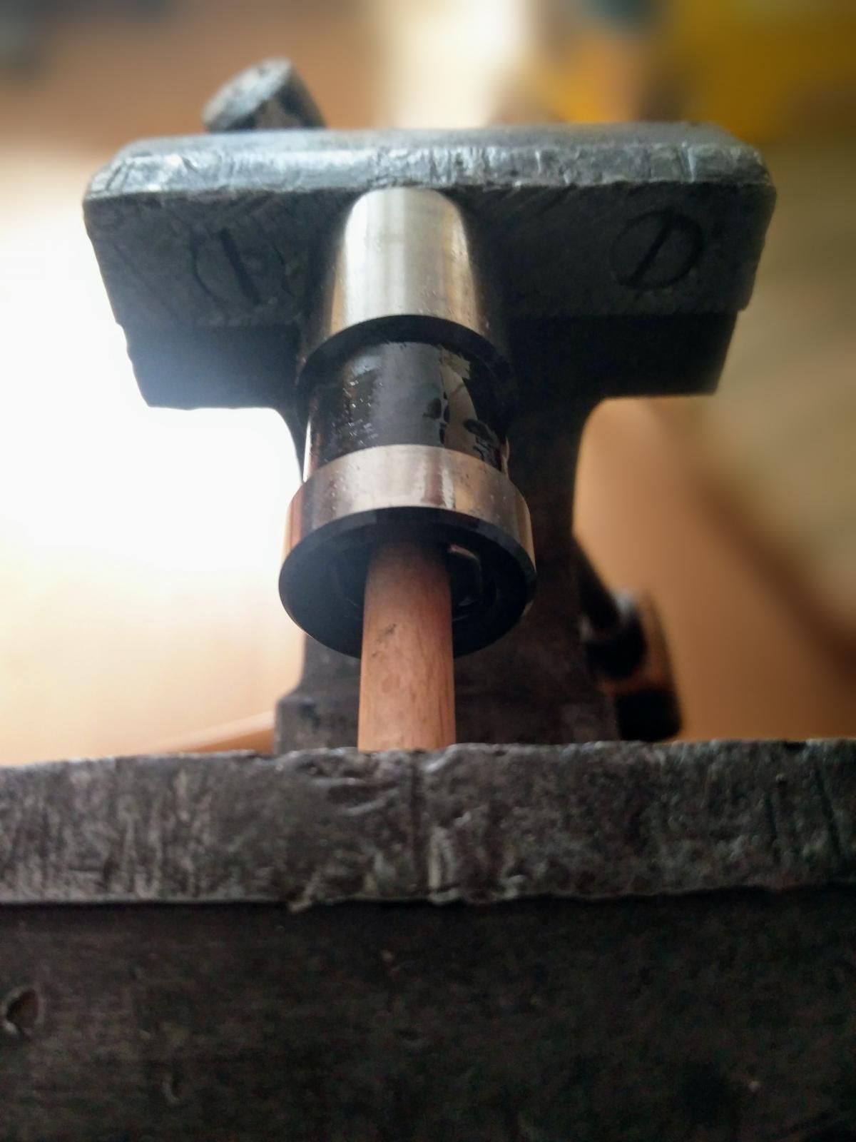
- Insert pushrod in socket and slowly press together in vise (bore must face upwards) until lock ring can be installed.
👉 Notice how the socket will beetle a fleck, as you cannot push information technology farther down with your fingers. That'southward what the vise will be for.
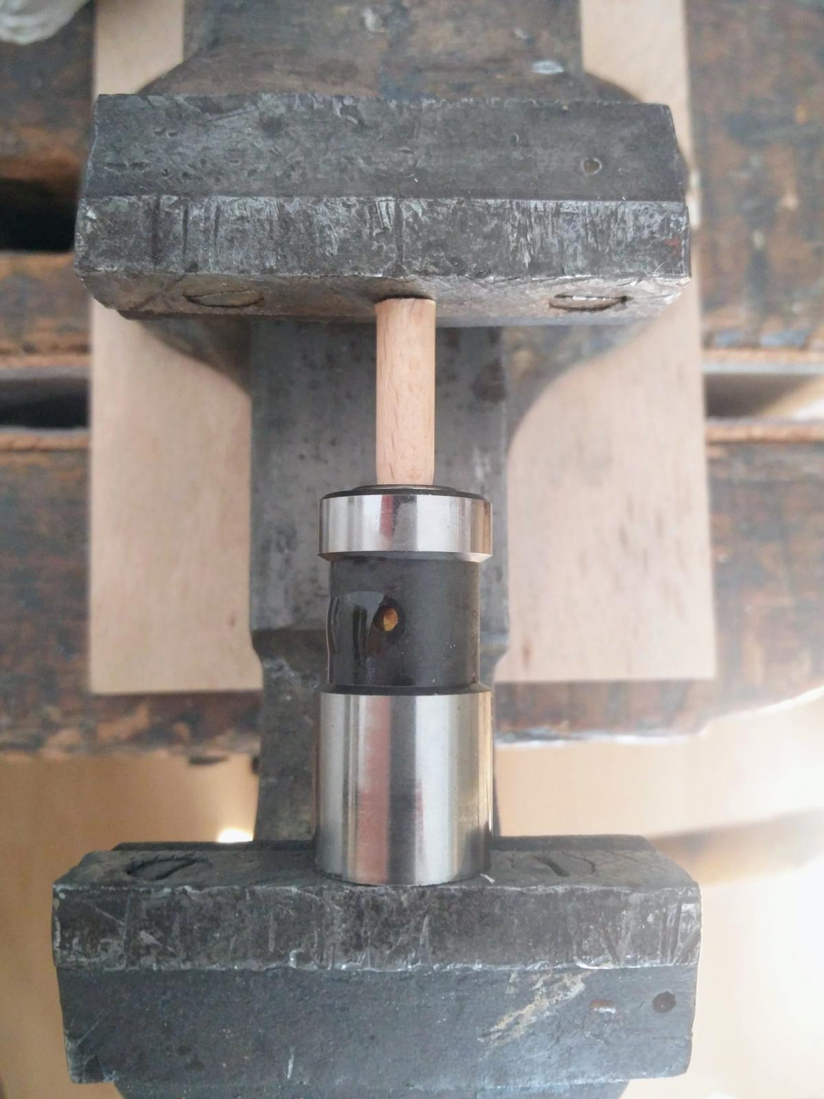
👉 Make certain the dowel is truly perpendicular to the lifter and the vise grip. Really, cheque it out. If it's not, both dowel and lifter might snap out of the vise under pressure. You don't desire to damage the lifter, or virtually importantly, yourself.
💡 Find how oil is seeping out of the drain/feed hole equally yous push button. I'd recommend pressing slowly, waiting for oil to come out a bit, then cleaning up, then turning the vise once again.
💡 Oil will also seep out from the meridian of the pushrod socket. Recall controlled bleeding is also happening there to send oil up the hollow pushrod. Every bit our pushrod substitute here is not hollow, oil will escape through the sides of the socket, every bit the oil has nowhere else to go to otherwise.
💡 You are effectively doing the same action as when adjusting the lifter's preload on the coach. Simply that here you will get as far as the lock ring groove, not further.
- Install lock ring
eight. You lot're done
Reference
- Hydraulic lifters by Richard Atwell, for Vanagon lifters
- Bleeding and cleaning hydraulic lifters past Christopher Schimke, for Vanagon lifters
- Adjusting hydraulic lifters later a rebuild
The motivation for this guide was to provide easy, step-by-step instructions for the procedure, specific to the Type 2 bus.
Other than the fact that there was no such written material, there seemed to be some defoliation about the procedure, particularly because:
- Richard Atwell has an extensive and excellent article nigh hydraulic lifters, merely it does not mention the manual bleeding process. It as well shows lifters with a different pattern than the ones used in 78-79 buses.
- The Type 2 (Bay Window) Bentley manual describes a process that is fairly cumbersome, involving submerging the lifters in oil and using a press, which almost hobbyists will not accept.
Reportedly, the Waterboxer Vanagon Bentley Manual instructions were easier to follow and make more than sense than the Bay Window Bentley ones. I tried them, and they worked beautifully. This guide is the result of using that method specifically for the hydraulic valve lifters used in the late jitney Type 4 engine.
Source: https://davidplanella.org/how-to-bench-bleed-hydraulic-valve-lifters/
0 Response to "How To Fill Hydraulic Lifters With Oil"
Post a Comment